Showing posts with label Mikrotik Tips. Show all posts

Wednesday, May 1, 2013

OpenWRT on Mikrotik Routerboard 411/750

Introduction

The Mikrotik Routerboards are cheap and versatile embedded platforms that can be used for routers, WiFi APs and the like. In a rather wide range of products, I happen to have access to the RB411 and the RB750 two devices of very different properties. While the RB750 is effectively a 5 port 10/100 Mbit Ethernet switch with an Atheros AR71xx CPU on it, the RB411 has the same CPU with one Ethernet port and a Mini PCI slot as well as a serial port (and a beeper ;) ). Because of their price (around 40 €), both are very interesting targets to do some experiments with them. Unfortunately, they come with Mikrotiks RouterOS which seems to be a modified Linux that officially cannot be modified. Interestingly, the RB do not ship with a GPL and as far as I have heard, Mikrotik does not publish the source code as required by the GPL. So, who wants RouterOS anyway? ;)
Although I do not have other Mikrotik products, I assume that the OpenWRT flash procedure is similar for products using RouterBOOT as bootloader and the Atheros AR71xx CPU. However, this guide comes without warranty, everything you do is at your full risk. Although I was unable to do so, there is a certain risk of permanently bricking your device.
The process of flashing the Routerboard has 5 major steps:
  1. Prepare an OpenWRT Ramdisk Image
  2. Prepare the OpenWRT target Image
  3. Configure the TFTP and DHCP Server
  4. Boot the Routerboard using the Ramdisk Image
  5. Flash the Target Image

Preparation Procedure

Prepare an OpenWRT Ramdisk Image

Compiling OpenWRT from the SVN is actually more straight forward than you might imagine. Take your favorite Linux Distribution (Ubuntu in my case), check our the SVN, configure it and hit make. There you go.
  1. Get the source code
    Check out the latest and greatest version of OpenWRT: I have used revision 27019.
  2. Configure OpenWRT according to your needs
    1
    2
    cd trunk
    make menuconfig
    While you are of course free to select all the packages you need and deselect those you do not need, you have to set the following options to make it work in the Routerboards:
    1
    2
    3
    Target System: Atheros AR71xx
    Subtarget: Devices with NAND flash (mostly Mikrotik)
    Target Images: ramdisk
  3. Build it
    The build process of OpenWRT takes a long time, but is very simple:
    1
    make
    The result image is located in the bin/ar71xx directory and is called openwrt-ar71xx-nand-vmlinux-initramfs.elf.

Prepare the OpenWRT target Image

  1. Configure OpenWRT according to your needs
    1
    2
    cd trunk
    make menuconfig
    This time, you have to change the Target Images to tar.gz as follows:
    1
    2
    3
    Target System: Atheros AR71xx
    Subtarget: Devices with NAND flash (mostly Mikrotik)
    Target Images: tar.gz
  2. Build it
    1
    make
    The target image consists of two files in the bin/ar71xx directory:
    • Kernel Image: openwrt-ar71xx-nand-vmlinux.elf
    • Root File System: openwrt-ar71xx-nand-rootfs.tar.gz

Configure the TFTP and DHCP Server

  1. Configure your network Interface
    The network interface to which the Routerboard is connected must have a unique IP with a DHCP running on it. To make debugging easier, it is usually a good idea to directly connect the Routerboard to your NIC without other devices involved.
    Configure the Interface within the subnet 192.168.1.0/24 (OpenWRTs default subnet) but try to avoid 192.168.1.1 (OpenWRTs default IP). I have used 192.168.1.2.
  2. Install DHCP and TFTP Servers
    You will need a DHCP Server to assign an IP address to the Routerboard for the flash process. Also, the DHCP server tells the board which file to use as image. Frankly, the tftp Server is responsible to provide the image file to the RB.
    On Ubuntu Linux, I have used these packages:
    1
    apt-get install dhcp3-server atftpd
  3. Configure the DHCP Server
    The DHCP Server does not need much configuration. I use the following as /etc/dhcp3/dhcpd.conf:
    1
    2
    3
    4
    5
    6
    7
    8
    9
    10
    11
    12
    13
    allow booting;
    allow bootp;
     
    subnet 192.168.1.0 netmask 255.255.255.0 {
      range 192.168.1.10 192.168.1.200;
    }
     
    host routerboard {
      hardware ethernet 00:0c:42:XX:YY:ZZ;
      fixed-address 192.168.1.100;
      next-server 192.168.1.2;
      filename "openwrt-ar71xx-nand-vmlinux-initramfs.elf";
    }
    You may want to modify the IP range to match your subnet, the hardware ethernet MAC address of your router board, the next-server address of your tftp server and the filename of the ramdisk image that should be booted over the network.
  4. Configure the TFTP Server
    Edit /etc/default/atftps to avoid running the daemon over inetd. My file looks like this:
    1
    2
    USE_INETD=false
    OPTIONS="--tftpd-timeout 300 --retry-timeout 5 --mcast-port 1758 --mcast-addr 239.239.239.0-255 --mcast-ttl 1 --maxthread 100 --verbose=5 /tftpboot"
    You can see, that the tftp server will look for image files in /tftpboot. Either change this directory or copy the OpenWRT ramdisk image (openwrt-ar71xx-nand-vmlinux-initramfs.elf) to /tftpboot.
    1
    cp bin/ar71xx/openwrt-ar71xx-nand-vmlinux-initramfs.elf /tftpboot
  5. Apply the changed configuration
    1
    2
    /etc/init.d/dhcp3-server reload
    /etc/init.d/atftpd reload

Flash process for Routerboard 750

Booting the Ramdisk Image

The purpose of this step is to have a ramdisk version of OpenWRT running on the routerboard. This is a good basis for our flashing process and can also be used to test images without flashing them. This involves the following steps:
  1. Connecting the Routerboard
    Connect port 1 of the Routerboard with the Ethernet port that your DHCP and TFTP server listens on.
  2. Boot the Routerboard
    Now press and hold the “RES” button of the router board and connect power. Both LEDs (PWR and ACT) will be constantly on, keep pressing the button. After some seconds the “ACT” LED starts flashing, keep pressing. After some more seconds, the “ACT” LED turns off, now you can stop pressing the button. The board will now try to obtain an IP address via DHCP/BOOTP and then download and boot the Ramdisk image. You can see this activity by looking at the appropriate log files:
    1
    tail -f /var/log/daemon.log /var/log/messages
    You should see something like this:
    1
    2
    3
    May 27 13:21:26 tk dhcpd: BOOTREQUEST from 00:0c:42:XX:YY:ZZ via eth1
    May 27 13:21:26 tk dhcpd: BOOTREPLY for 192.168.1.101 to routerboard (00:0c:42:XX:YY:ZZ) via eth1
    May 27 13:21:26 tk atftpd[26400]: Serving openwrt-ar71xx-nand-vmlinux-initramfs.elf to 192.168.1.101:33321
    Sit and wait until 192.168.1.1 starts replying to pings. Now you can log into the board using telnet (ssh login is not possible, since no password is set as of yet).
    1
    telnet 192.168.1.1
  3. Flash the target Image

  4. Erase the flash memory
    You can look at the existing flash partitions by looking at /proc/mtd.
    1
    2
    3
    4
    5
    root@OpenWrt:~# cat /proc/mtd
    dev:    size   erasesize  name
    mtd0: 00040000 00004000 "booter"
    mtd1: 003c0000 00004000 "kernel"
    mtd2: 03c00000 00004000 "rootfs"
    Now, erase the content of “kernel” and “rootfs”:
    1
    2
    mtd erase kernel
    mtd erase rootfs
  5. Create new file systems
    After erasing the content of the flash, we now need to create new yaffs2 partitions. In principle, we could also make the rootfs ext2/3/4, but I have not tried this. The kernel partition has to be yaffs2 as far as I know to be compatible with the bootloader.
    1
    2
    3
    mkdir /mnt/kernel /mnt/rootfs
    mount -t yaffs2 /dev/mtdblock1 /mnt/kernel
    mount -t yaffs2 /dev/mtdblock2 /mnt/rootfs
  6. Copy the images onto the Routerboard
    Copying the images onto the routerboard can be done in multiple ways, I have used secure file copy (scp). First, we have to create a password for the root user. On the routerboard, execute
    1
    passwd
    and set a password. On the linux PC, you can now copy the images onto the Routerboard:
    1
    scp bin/ar71xx/openwrt-ar71xx-nand-rootfs.tar.gz bin/ar71xx/openwrt-ar71xx-nand-vmlinux.elf root@192.168.1.1:/tmp
  7. Flash the images onto the Routerboard
    Flashing the images is simple, once you have them on the Routerboard. First, the kernel:
    1
    2
    3
    mv /tmp/openwrt-ar71xx-nand-vmlinux.elf /mnt/kernel/kernel
    chmod +x /mnt/kernel/kernel
    umount /mnt/kernel
    Now the root filesystem:
    1
    2
    3
    4
    cd /mnt/rootfs
    tar -xvzf /tmp/openwrt-ar71xx-nand-rootfs.tar.gz
    cd /
    umount /mnt/rootfs
  8. That’s it, you are done
    Finally, reboot the routerboard.
    1
    reboot
    After some while, you should be able to ping the board at 192.168.1.1.

What if the Routerboard does not boot?

Do not panic. If the board is not reachable at 192.168.1.1 after some minutes, something must have gone wrong. You can always recover the boards using Mikrotiks Netinstall. Also, you can start again at the point where the ramdisk image should have booted. Unfortunately, the RB750 does not have a serial port, debugging problems with the linux boot process is probably *very* annoying.

Flash process for Routerboard 411

The flash process for the Routerboard 411 is almost similar to the process for the RB750 – only the flash layout is a bit different and hence the number of the target partitions have to be changed. Apart from that, you can use the exact same procedure. However, since the RB411 offers a serial port, debugging is much more convenient.

Booting the Ramdisk Image

The purpose of this step is to have a ramdisk version of OpenWRT running on the routerboard. This is a good basis for our flashing process and can also be used to test images without flashing them. This involves the following steps:
  1. Connecting the Routerboard
    Connect the Ethernet port of the Routerboard with the Ethernet port that your DHCP and TFTP server listens on.
  2. Configure the Bootloader
    Connect a serial cable to the serial port of the routerboard using the settings 115200 8n1. The boot process should look similar to this:
    1
    2
    3
    4
    5
    6
    7
    8
    RouterBOOT booter 2.27
     
    RouterBoard 411
     
    CPU frequency: 300 MHz
      Memory size:  32 MB
     
    Press any key within 2 seconds to enter setup
    Press any key and you will end up here:
    1
    2
    3
    4
    5
    6
    7
    8
    9
    10
    11
    12
    13
    14
    15
    16
    17
    18
    RouterBOOT-2.27
    What do you want to configure?
       d - boot delay
       k - boot key
       s - serial console
       n - silent boot
       o - boot device
       u - cpu mode
       f - cpu frequency
       r - reset booter configuration
       e - format nand
       g - upgrade firmware
       i - board info
       p - boot protocol
       b - booter options
       t - do memory testing
       x - exit setup
    your choice:
    Change the “boot device” (o) to “boot over Ethernet” (e). Reboot with x.
  3. Boot the Routerboard
    While looking at the serial terminal, you should see something like:
    1
    2
    3
    4
    5
    6
    7
    8
    9
    10
    11
    12
    RouterBOOT booter 2.27
     
    RouterBoard 411
     
    CPU frequency: 300 MHz
    Memory size:  32 MB
     
    Press any key within 2 seconds to enter setup..
    trying bootp protocol... OK
    Got IP address: 192.168.1.100
    resolved mac address 00:E0:4C:XX:YY:ZZ
    transfer started ..........................
  4. Flash the target Image

  5. Erase the flash memory
    You can look at the existing flash partitions by looking at /proc/mtd.
    1
    2
    3
    4
    5
    6
    7
    8
    9
    10
    root@OpenWrt:~# cat /proc/mtd
    root@OpenWrt:/# cat /proc/mtd
    dev:    size   erasesize  name
    mtd0: 0000b000 00001000 "routerboot"
    mtd1: 00001000 00001000 "hard_config"
    mtd2: 00002000 00001000 "bios"
    mtd3: 00001000 00001000 "soft_config"
    mtd4: 00040000 00004000 "booter"
    mtd5: 005c0000 00004000 "kernel"
    mtd6: 03a00000 00004000 "rootfs"
    Now, erase the content of “kernel” and “rootfs”:
    1
    2
    mtd erase kernel
    mtd erase rootfs
  6. Create new file systems
    After erasing the content of the flash, we now need to create new yaffs2 partitions. In principle, we could also make the rootfs ext2/3/4, but I have not tried this. The kernel partition has to be yaffs2 as far as I know to be compatible with the bootloader.
    1
    2
    3
    mkdir /mnt/kernel /mnt/rootfs
    mount -t yaffs2 /dev/mtdblock5 /mnt/kernel
    mount -t yaffs2 /dev/mtdblock6 /mnt/rootfs
  7. Copy the images onto the Routerboard
    Copying the images onto the routerboard can be done in multiple ways, I have used secure file copy (scp). First, we have to create a password for the root user. On the routerboard, execute
    1
    passwd
    and set a password. On the linux PC, you can now copy the images onto the Routerboard:
    1
    scp bin/ar71xx/openwrt-ar71xx-nand-rootfs.tar.gz bin/ar71xx/openwrt-ar71xx-nand-vmlinux.elf root@192.168.1.1:/tmp
  8. Flash the images onto the Routerboard
    Flashing the images is simple, once you have them on the Routerboard. First, the kernel:
    1
    2
    3
    mv /tmp/openwrt-ar71xx-nand-vmlinux.elf /mnt/kernel/kernel
    chmod +x /mnt/kernel/kernel
    umount /mnt/kernel
    Now the root filesystem:
    1
    2
    3
    4
    cd /mnt/rootfs
    tar -xvzf /tmp/openwrt-ar71xx-nand-rootfs.tar.gz
    cd /
    umount /mnt/rootfs
  9. Reconfigure the Bootloader
    Reboot the board and enter the bootloader. Now change the boot device (o) to “boot from NAND, if fail then Ethernet” (n). Save settings with x.
  10. That’s it, you are done
    After some while, you should be able to ping the board at 192.168.1.1.
What if the Routerboard does not boot?

Do not panic. Look onto the serial terminal to see, at which state the Routerboard is stuck. You can always recover the boards using Mikrotiks Netinstall.

Manual:Netinstall Mikrotik

NetInstall Description

NetInstall is a program that runs on Windows computer that allows you to install MikroTiK RouterOS onto a PC or onto a RouterBoard via an Ethernet network.

NetInstall is also used to re-install RouterOS in cases where the the previous install failed, became damaged or access passwords were lost.
  • Your device must support booting from ethernet, and there must be a direct ethernet link from the Netinstall computer to the target device. All RouterBOARDs support PXE network booting, it must be either enabled inside RouterOS "routerboard" menu if RouterOS is operable, or in the bootloader settings. For this you will need a serial cable.
Note: For RouterBOARD devices with no serial port, and no RouterOS access, the reset button can also start PXE booting mode. See your RouterBOARD manual PDF for details. 
  • Netinstall can also directly install RouterOS on a disk (USB/CF/IDE/SATA) that is connected to the Netinstall Windows machine. After installation just move the disk to the Router machine and boot from it.

Interface

The following options are available in the Netinstall window:
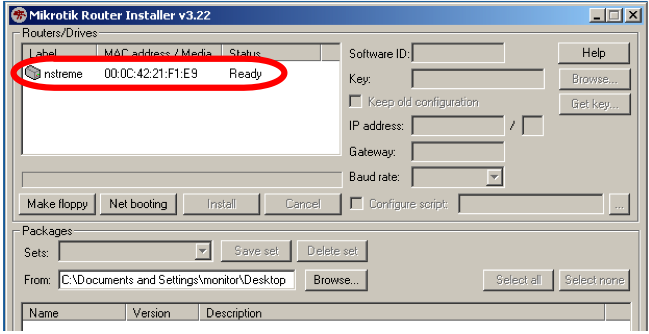
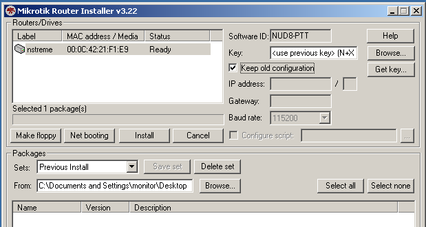
  • Routers/Drives - list of PC drives, and in the routers that were detected near the Netinstall PC
  • Make floppy - used to create a bootable 1.44" floppy disk for PCs which don't have Etherboot support
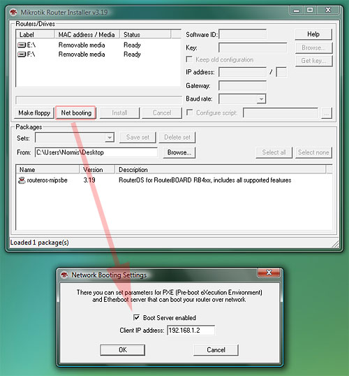
  • Net booting - used to enable PXE booting over network (your default choice)
  • Install/Cancel - after selecting the router and selecting the RouterOS packages below, use this to start install
  • SoftID - the SoftID that was generated on the router. Use this to purchase your key
  • Key / Browse - apply the purchased key here, or leave blank to install a 24h trial
  • Get key - get the key from your mikrotik.com account directly
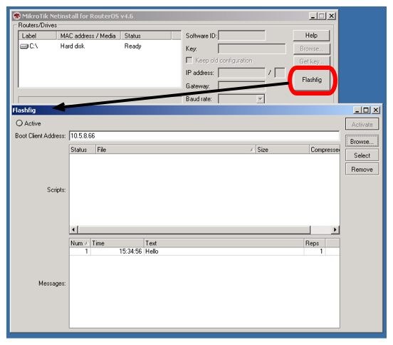
  • Flashfig - launch Flashfig - the mass config utility which works on brand new devices
  • Keep old configuration - keeps the configuration that was on the router, just reinstalls software (no reset)
  • IP address / "Netmask - enter IP address and netmask in CIDR notation to preconfigure in the router
  • Gateway - default gateway to preconfigure in the router
  • Baud rate - default serial port baud-rate to preconfigure in the router
  • Configure script File that contains RouterOS CLI commands that directly configure router (e.g. commands produced by export command). Used to apply default configuration

Screenshot

2009-01-27 1224.jpg
  • for installation over network, don't forget to enable the PXE server, and make sure Netinstall is not blocked by your firewall or antivirus. The connection should be directly from your Windows PC to the Router PC (or RouterBOARD), or at least through a switch/hub.


NetInstall Example

This is a step by step example of how to install RouterOS on a RouterBoard 532 from a typical notebook computer.

Requirements

The Notebook computer must be equiped with the following ports and contain the following files:
  • Ethernet port.
  • Serial port.
  • Serial communications program (such as Hyper Terminal)
  • The .npk RouterOS file(s) (not .zip file) of the RouterOS version that you wish to install onto the Routerboard.
  • The NetInstall program available from the Downloads page at www.mikrotik.com

Connection process

  1. Connect the routerboard to a switch, a hub or directly to the Notebook computer via Ethernet. The notebook computer Ethernet port will need to be configured with a usable IP address and subnet. For example: 10.1.1.10/24
  2. Connect the routerboard to the notebook computer via serial, and establish a serial communication session with the RouterBoard. Serial configuration example in in the Serial console manual
  3. Run the NetInstall program on your notebook computer.
  4. Press the NetInstall "Net Booting" button, enable the Boot Server, and enter a valid, usable IP address (within the same subnet of the IP address of the Notebook) that the NetInstall program will assign to the RouterBoard to enable communication with the Notebook computer. For example: 10.1.1.5/24
  5. Set the RouterBoard BIOS to boot from the Ethernet interface.

Configuring RouterBOARD

Configuring RouterBOARD without COM port
  • To boot RouterBOARD withtout COM port from Network, you can use reset button. Consult RouterBOARD.com and specific RouterBOARD User Guide to find reset button location and usage instructions. For example RB751U-2HnD etherboot instructions,
RouterBOARD 751U-2HnD RouterBOOT reset button (RES, front panel) has two functions to reset RouterOS configuration and boot it from Etherboot: - Connect Netinstall PC to "ether1" port and hold this button during boot time longer, until LED turns off, then release it to make the RouterBOARD look for Netinstall servers.
  • As well Etherboot can be configured by RouterOS (when you have access to it),
system routerboard settings set boot-device=try-ethernet-once-then-nand
Configuring RouterBOARD with COM port
To access Routerboard BIOS configuration: reboot the Routerboard while observing the activity on the Serial Console. You will see the following prompt on the Serial Console “Press any key within 2 seconds to enter setup” indicating that you have a 1 or 2 second window of time when pressing any key will give you access to Routerboard BIOS configuration options.
(press any key when prompted):
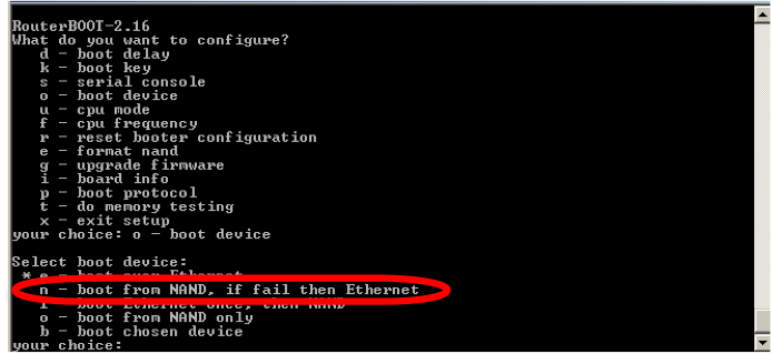
You will see the following list of available BIOS Configuration commands. To set up the boot device, press the 'o' key:


What do you want to configure?
  d - boot delay
  k - boot key
  s - serial console
  l - debug level
  o - boot device
  b - beep on boot
  v - vga to serial
  t - ata translation
  p - memory settings
  m - memory test
  u - cpu mode
  f - pci back-off
  r - reset configuration
  g - bios upgrade through serial port
  c - bios license information
  x - exit setup

Next Selection: Press the 'e' key to make the RouterBoard to boot from Ethernet interface:
Select boot device:
* i - IDE
  e - Etherboot
  1 - Etherboot (timeout 15s), IDE
  2 - Etherboot (timeout  1m), IDE
  3 - Etherboot (timeout  5m), IDE
  4 - Etherboot (timeout 30m), IDE
  5 - IDE, try Etherboot first on next boot (15s)
  6 - IDE, try Etherboot first on next boot (1m)
  7 - IDE, try Etherboot first on next boot (5m)
  8 - IDE, try Etherboot first on next boot (30m)

The RouterBoard BIOS will return to the first menu. Press the 'x' key to exit from BIOS. The router will reboot.
  • Make sure boot-protocol is bootp.

Installation

Watch the serial console as the RouterBoard reboots, it will indicate that the RouterBoard is attempting to boot to the NetInstall program. The NetInstall program will give the RouterBoard the IP address you entered at Step 4 (above), and the RouterBoard will be ready for software installation. Now you should see the MAC Address of the RouterBoard appear in the Routers/Drives list of the NetInstall program.
NetinstallStart.png
Click on the desired Router/Drive entry and you will be able to configure various installation parameters associated with that Router/Drive entry.
Nconfig.PNG
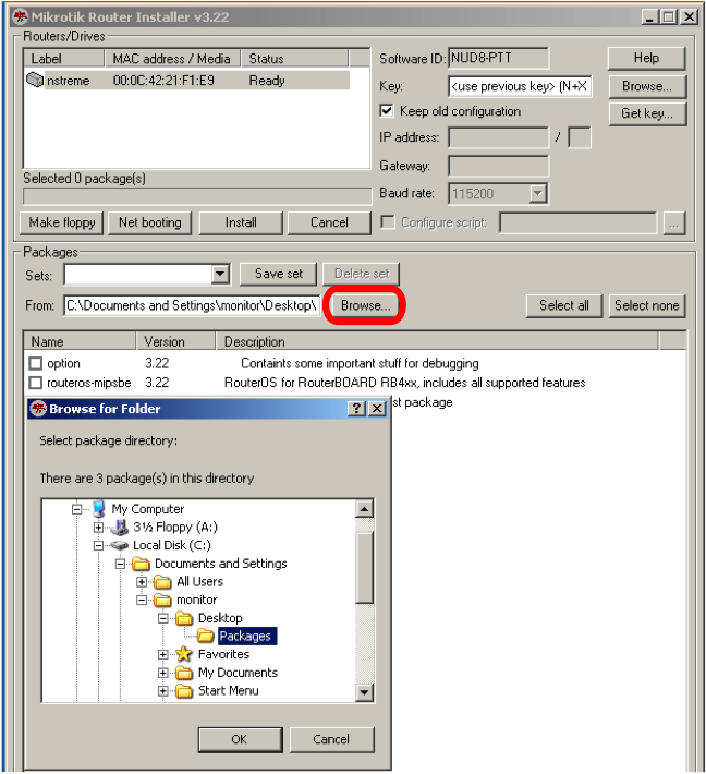
For most Re-Installations of RouterOS on RouterBoards you will only need to set the following parameter:
Press the "Browse" button on the NetInstall program screen. Browse to the folder containing the .npk RouterOS file(s) of the RouterOS version that you wish to install onto the Routerboard.
NConfig3.png
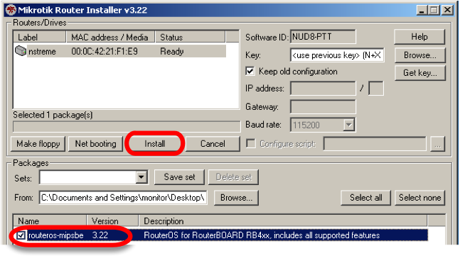
When you have finalized the installation parameters, press the "Install" button to install RouterOS.
NetinstallC4.png
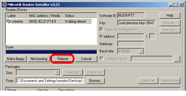
When the installation process has finished, press 'Enter' on the console or 'Reboot' button in the NetInstall program.
NetinstallC5.png

Cleanup

1. Reset the BIOS Configuration of the RouterBoard to boot from its own memory.
NetinstallC6.png
2. Reboot the RouterBoard.


Reset RouterOS Password

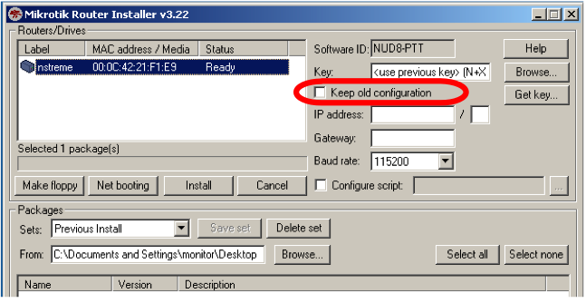
Netinstall can be used to reset password of RouterOS by erasing all configuration from the router. Uncheck 'Keep Old Configuration' during Netinstall and proceed with standard procedure,
PasswordReset.png

Manual:Flashfig Mikrotik

Description

Flashfig is an application for mass router configuration. It can be used by MikroTik distributors, ISPs or any other companies who need to apply RouterOS configuration to many routers in shortest possible time.

Flashfig applies MikroTik RouterOS configuration to any RouterBOARD within 3 seconds. You can "flashfig" batch of routers, the only thing you need - connect RouterBOARD to network and power it.

Flashfig runs on a Windows computer, Flashfig is available within Netinstall.

Flashfig is supported by all RouterBOARDs. It works between computer with Flashfig and RouterBOARD in the same broadcast domain (direct Ethernet network connection is required).
Flashfig support is enabled on every new RouterBOARD by default from factory (RouterBOARDs manufactured after March 2010). For older models, Flashfig can be enabled via RouterBOOT or from MikroTik RouterOS console.

After Flashfig is used once on a brand new RouterBOARD, it is disabled to avoid unwanted reconfiguation at later time. To use Flashfig a second time on the same router, you need to enable it in Bootloader settings.
If RouterOS reset-configuration command is used later, Flashfig configuration is not loaded, but RouterOS default configuration.
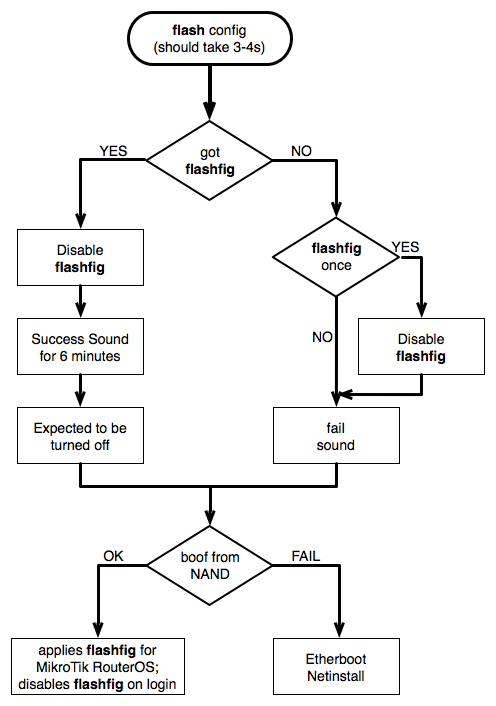
Flashfig diagram shows the procedure of Flashfig, Flashfigdiagramm.png

Flashfig Example

This is a step by step example of how to use Flashfig to set typical MikroTik RouterOS configuration to RouterBOARD.

Introduction

Flashfig is available from Netinstall,
Flashfig.png

Requirements

The Windows computer must be equipped with the following ports and contain the following files:
  • Ethernet port;
  • The .rsc file(s) with MikroTik RouterOS configuration (the same as export/import file);
  • The latest NetInstall/Flashfig program available from the downloads page;
The RouterBOARD:
  • Flashfig is supported by first boot of RouterBOARD;

Pre-Configuration

Windows Computer
  • Run Flashfig;
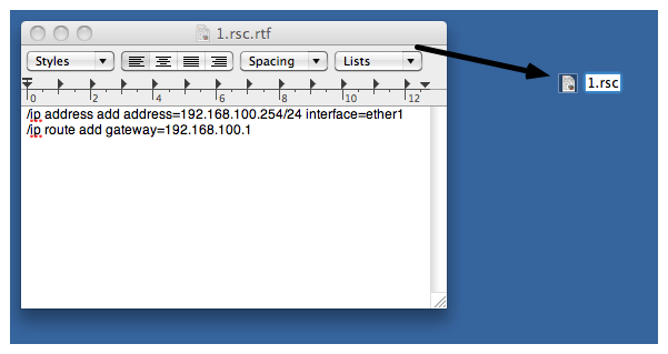
  • Prepare .rsc file, .rsc file is regular/import file, it accepts valid MikroTik RouterOS CLI commands. You can create .rsc file by any text-editor program (Notepad, Texteditor, TextEdit, Microsoft Word, OpenOffice Writer);
Flashfig2.png
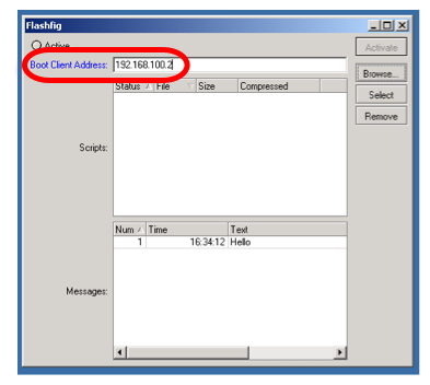
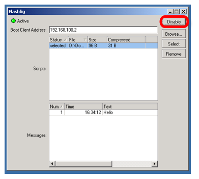
  • Assign Boot Client Address, which should be address from the same subnet as configured on laptop Ethernet interface,
Flashfig3.png
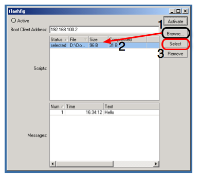
  • Browse for .rsc MikroTik RouterOS configuration file to apply to RouterBOARD, highlight the file and Select to approve it,
Flashfig4.png
  • Activate Flashfig server, now it is ready to Flashfig. Note, any RouterBOARD will be flashfiged within the network, which is powered on with boot-device configured to flash-boot or flash-boot-once-then-nand,

Flashfig5.png
RouterBOARD
  • Flashfig mode is enabled on every RouterBOARD from factory by default, which means no configuration is required on RouterBOARD.
  • If Flashfig is not enabled on your router, access the RouterBOARD with Winbox/Console and set the configuration,
/system routerboard settings set boot-device=flash-boot
or use more preferable option,
/system routerboard settigs set boot-device=flash-boot-once-then-nand
Your router is now ready for Flashfig.

Connect

Connect RouterBOARD and Flashfig computer to the same Local Area Network.

Run Flashfig

  • Plug power for RouterBOARD
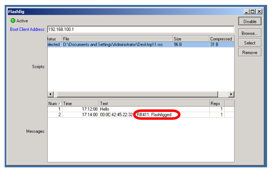
  • Check the status on Flashfig program,
Flashfig6.png
Log shows "RouterBOARD Flashfigged" and RouterBOARD should make sound/LED signal, now it is safe to unplug the router.

Mikrotik Metal 2SHPn Configurations


Configure Mikrotik Metal 2SHPn

Configuration of Mikrotik Metal 2SHPn is the same as we did in Mikrotik Groove A2hn,there  is a new feature in called “Quick Setup” i will explain this feature in this post.
The first and foremost step is to Connect  Mikrotik Metal 2SHPn to your system and turn on the device.
Make sure you have made the PoE connections correctly. Check that you have connected the PoE cable to  Mikrotik Metal 2SHPn and  LAN to your computer.
After connecting all the cables,now its time to discover the device on the Winbox discovery.You can download winbox from here.
Open your winbox and click on the box near Connect Button saying “… ” (Click again and again if it does not discover).
Select the Mac of your device from the list and click on Connect.
Note:Keep the following points in mind before discovering through winbox:
  • Make sure you winbox discovery in not disabled (However it is enabled by default)
  • Make sure your windows firewall is not blocking the winbox discovery
  • Make sure your antivirus is not blocking the winbox discovery

 Configure Mikrotik Metal 2SHPn as access point

The First option in Mikrotik Metal 2SHPn’s interface is the Quick Set.The Quick Set feature allows you to set up your wireless very quickly. Let’s discuss it features
At the top left corner, you can see a drop down menu, you can select the Mode, whether you want it for AP, Bridge or Client
Here I am selecting it to AP as I am configuring it as Access Point
Select your Network name in SSID field,

In frequency,Select any of the 13 frequencies.(This is also called Channel,Use the channel which is not used by others.You can find others channels by clicking on SCAN)
In Band, Set Band to 2Ghz B/G/N.
B mode gives you 11 Mbps throughput.
G mode gives you 54 Mbps throughput.
and N mode gives you 150 Mbps throughput.(N mode will only work if you have channel width 40 Mhz)
Set channel width to 20 Mhz if you want to connect 20Ghz enabled devices like Tl-Wa 500g,But 40Ghz is recomended.(But N mode will not work)
Set channel width to 40 Mhz if you want more throughput.
Select your Country.
Select Configuration mode to bridge
Set your IP address to static so that your can configure it through web interface.
Enter Ip address, Gateway and DNS according to your network scenario.
Router Identity is the name of your Device,whenever you will discover it in DHCP Pool you will see its Identity name.
You can also change it Password from Quick setup.
These are the Settings for Mikrotik Metal 2SHPn’s wireless.The other settings are same as in Mikrotik Groove a2hn.

Security settings for  Mikrotik Metal 2SHPn

Goto Wireless,Click on security profile,Enter a profile name like WPA-2PSK security.
In mode,select Dynamic Keys
I would like to recommend WPA2 PSK security as it is very tight security.

Enter you security keys in WPA2 pre shared key

Enabling internet sharing in  Mikrotik Metal 2SHPn

Now its time to enable internet sharing in  Mikrotik Metal 2SHPn,
First create a bridge which will connect the wlan and ether 1 with one another.

Click on Bridge,and click on + Sign,Click OK


Now click on ports and click on + Sign Select interface to Ether1 and bridge to Bridge1. 

  Again click on ports and click on + Sign Select interface to wlan1 and bridge to Bridge1.
Now click on IP > addresses and give an IP address to your LAN port.
Click on red + sign and enter IP Address 192.168.1.6/24 select interface to ether1

Now add a default gateway

Goto IP> Routes Click on red + sign and enter 192.168.1.1 in gateway field.

Now set DNS
Click on IP> DNS and click on DNS settings
Enter 8.8.8.8 as primary DNS
8.8.4.4 as Secondary DNS

Click apply and ok

Now its time to test your internet connectivity by connecting through a wireless device.

Mikrotik Metal 2shpn Trouble Shooting

Getting too high ping delay or disconnected due to extensive data loss

Metal 2shpn has a too much high output power which creates some problems like high ping delay or disconnection.You must try lowering  the output power,it creates this problem only to the nearer.Keep in mind, too much high power and too much signals will result in worse performance

Configure Hotspot in Mikrotik Groove A2hn Metal2shpn

Recently, I wrote two articles on the configurations of Mikrotik Groove A2hn and Mikrotik Metal 2shpn. And we learned howto configure them and share internet by creating a bridge.But many people, who bought Mikrotik Groove A2hn and  Metal2shpn,requested me to show howto configure Hotspot in Mikrotik Groove A2hn Metal2shpn. However the procedure is quite simple but i will tell you step by step for your ease.Let me first introduce what Hotspot means in Mikrotik?

Hotspot in Mikrotik  is the authentication method which allows the user to connect through their browser without using any software or driver.This is an HTTP base authentication method. This is an easy way to connect to your network because it always reminds the user to Login before using internet.It shows the Login page when user try to open any website.

Hope you have a cleared concept about hotspot in mikroitk.So, Lets start our work.

I highly recommend you not to configure Hotspot in Mikrotik Groove A2hn Metal2shpn because of low Ram and Processor.Configuring Hotspot in Mikrotik Groove A2hn Metal2shpn  may put an extra burden on your wireless device which will affect their performance.
You can configure hotspot in any mikrotik wireless router board in the same way.

Hotspot in Mikrotik Groove A2hn Metal2shpn.

We have came to know howto configure Mikrotik Groove A2hn and Metal2shpn wireless in our previous articles.That’s why I will not reconfigure their wireless section.If you have missed those articles, do have a look at
But do not enable Internet sharing.Follow the above posts till “Security settings”.
Goto IP > Addresses.
Click on “+” Sign to add an Ip address. In Ip address field add address: 192.168.1.2/24, Select interface ether1. Ether1 will act as a WAN or an internet gate.Click Apply and Ok.

Repeat the same process, Go to Ip > Addresses. Click on “+” Sign and now add address 192.168.5.1/24 and interface: wlan1. This will act as a LAN or out to users interface.Click Apply and Ok.
Now set DNS.

Click on IP> DNS and click on DNS settings.
Enter 8.8.8.8 as primary DNS.
8.8.4.4 as Secondary DNS.
Click apply and ok.
Now add a default gateway

Goto IP> Routes Click on red + sign and enter 192.168.1.1 in gateway field.

Npw goto Ip > Hotspot.
Click on “Hotspot Setup”.A new dialogue box will appear,Set Hotspot interface: Wlan1 and click Next.
Hotspot in Mikrotik Groove A2hn/Metal2shpn
Click next once again and make sure your “Local address of network ” is 192.168.5.1/24   .

Hotspot in Mikrotik Groove A2hn/Metal2shpn
Click Next again.

Hotspot in Mikrotik Groove A2hn/Metal2shpn
Click next.

Hotspot in Mikrotik Groove A2hn/Metal2shpn
Click next leaving the SMTP to 0.0.0.0.

Hotspot in Mikrotik Groove A2hn/Metal2shpn
Put DNS and click DNS. Ignore if DNS is already given.

Hotspot in Mikrotik Groove A2hn/Metal2shpn
Enter DNS Name : Login.wifitech.com.pk and click next.

d user
And now set default hotspot user and click next.

Hotspot in Mikrotik Groove A2hn/Metal2shpn
Finally, It will say that your setup has been completed successfully.

Now, we will make some changes to make mikrotik hotspot to work properly.

Hotspot settings
Double Click on “Servers” and set address per mac to “1″
Now go to Servers Profile and click on login, Uncheck cookies, apply and Ok.

Congratulations guys, You have successfully configured Hotspot in Mikrotik Groove A2hn Metal2shpn.Browser any web from client end,you will be prompted to a login page.Enter Username and password and enjoy…..

Thursday, April 18, 2013

Check and Update Routerboard BIOS firmware

The following article will discuss how to check and update the bios firmware version of mikrotik routerboard
How To check bios firmware version mikrotik routerboard :
* Login from winbox
* Use “New Terminal” and type this script   /system routerboard print
* The output like this
[admin@mikrotik] > system routerboard print
routerboard: yes
model: “450G”
serial-number: “XXXXXXXXXXXX”
current-firmware: “4.17″
upgrade-firmware: “5.15″

* Then upgrade with this script /system routerboard upgrade
* Wait for a seconds and your Bios Firmware now up to date, then reboot.

Upgrade Firmware Mikrotik (How To)

How To Upgrade Firmware Mikrotik
Here’s how to upgrade the firmware version of the product mikrotik. This method is applicable for almost all products on the market mikrotik.
Check the firmware version of mikrotik:
By using Winbox, go into terminal and type: / system routerboard then enter


shown in the picture, my mikrotik firmware version is 2:33, while the latest firmware version is 2:37.
how to upgrade the firmware version:
1. type in terminal: / system routerboard, then enter
2. after entry into the system routerboard directory, type: upgrade and then enter. select y (yes) to continue the upgrade process
3. wait a few moments to complete mikrotik firmware upgrade process


4. reboot mikrotik